
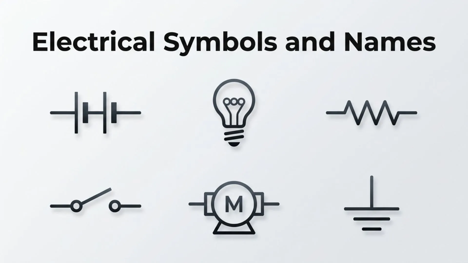
Electrical symbols are the universal language of electrical engineering, electronics, and wiring design. Instead of writing lengthy descriptions for every component, engineers and electricians use standardized symbols to represent devices, connections, and electrical functions in circuit diagrams and wiring schematics. These symbols make complex electrical systems easier to read, design, troubleshoot, and maintain.
Whether you’re a student learning basic electronics, an electrician working on residential wiring, or an engineer designing industrial control systems, understanding electrical symbols and names is an essential skill. From simple switches and resistors to transformers and circuit breakers, every symbol has a specific meaning and purpose.
This comprehensive guide explains the most common electrical symbols and names, their meanings, history, categories, practical applications, and tips for reading electrical diagrams with confidence.
Meaning and Overview of Electrical Symbols
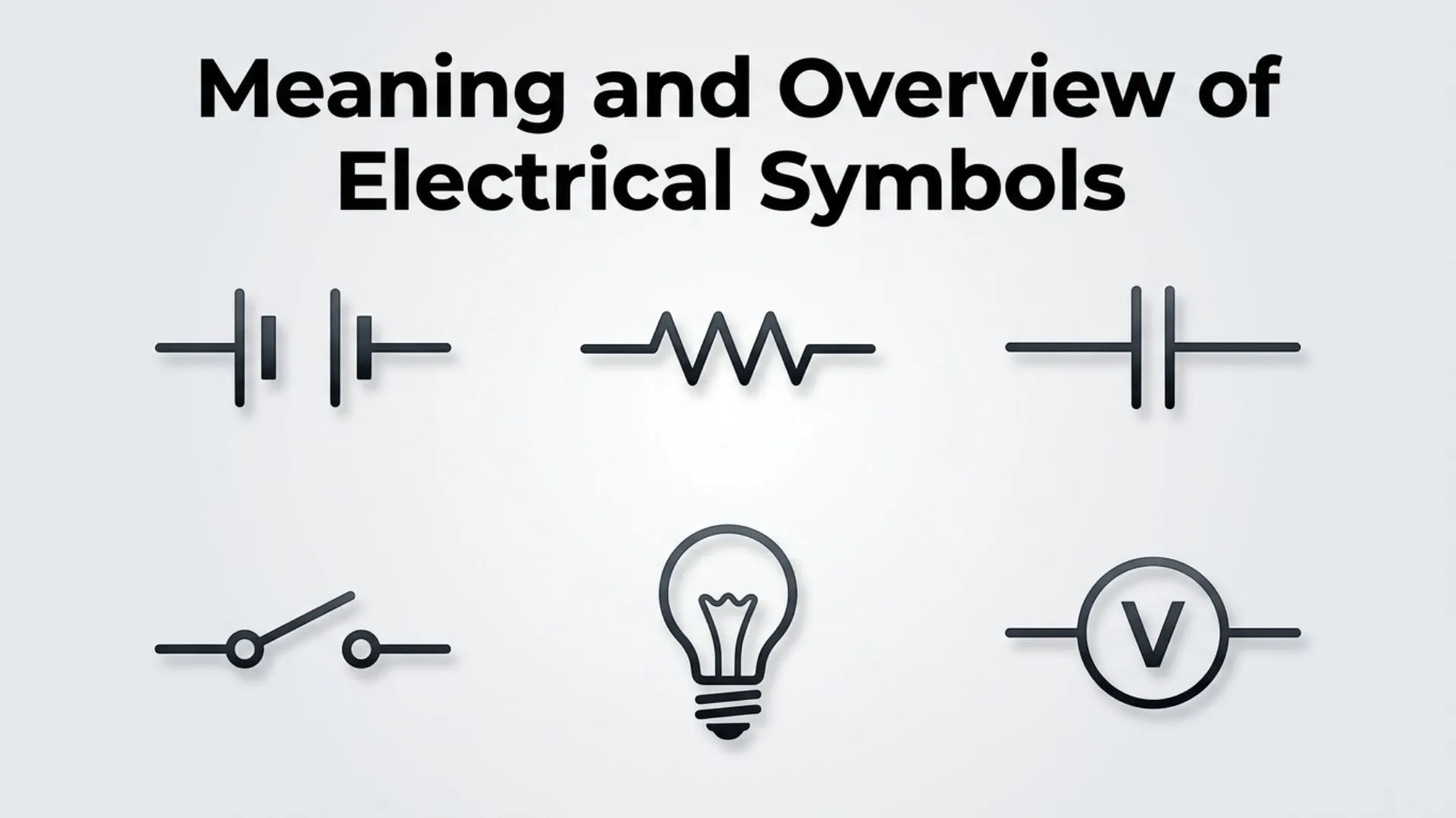
Electrical symbols are standardized graphical signs used to represent electrical and electronic components in circuit diagrams, blueprints, and technical drawings. Instead of showing the actual appearance of a device, each symbol provides a simplified visual representation that communicates its function.
These symbols help engineers, technicians, electricians, architects, and manufacturers understand electrical systems regardless of language or geographic location.
Standardized electrical symbols are defined by organizations such as the International Electrotechnical Commission (IEC), the Institute of Electrical and Electronics Engineers (IEEE), and national standards organizations. Using these common symbols ensures that electrical diagrams remain clear, accurate, and universally understandable.
History and Origin of Electrical Symbols
Electrical symbols have evolved alongside the development of electrical science. During the late 19th century, inventors and engineers created simple diagrams to document electrical circuits. As electrical systems became more sophisticated, the need for standardized symbols grew.
By the early 20th century, engineering organizations introduced official standards for representing electrical components. These standards reduced confusion and improved communication between manufacturers, electricians, and engineers.
Today, modern electrical symbols are used in:
- Residential wiring plans
- Commercial building designs
- Industrial automation
- Electronic circuit boards
- Renewable energy systems
- Automotive electrical diagrams
- Telecommunications equipment
Computer-aided design (CAD) software now includes extensive libraries of standardized electrical symbols for professional schematic design.
Types of Electrical Symbols and Names
Power Supply Symbols
Power supply symbols represent the source of electrical energy within a circuit.
Common examples include:
- AC Power Supply
- DC Power Supply
- Battery
- Battery Cell
- Generator
- Ground
- Earth Ground
- Chassis Ground
These symbols indicate where electricity originates and how it flows throughout the circuit.
Passive Component Symbols
Passive components control electrical current without generating power.
Resistor
A resistor limits the flow of electric current and protects sensitive components from excessive current.
Variable Resistor
Also called a potentiometer or rheostat, this component allows adjustable resistance in a circuit.
Capacitor
A capacitor stores electrical energy temporarily and releases it when needed.
Common capacitor symbols include:
- Fixed Capacitor
- Polarized Capacitor
- Variable Capacitor
Inductor
An inductor stores energy in a magnetic field and is commonly used in filters and power supplies.
Active Component Symbols
Active components control, amplify, or generate electrical signals.
Diode
A diode allows current to flow in only one direction.
Common diode types include:
- Standard Diode
- Zener Diode
- LED (Light Emitting Diode)
- Photodiode
- Schottky Diode
Transistor
Transistors act as electronic switches or amplifiers.
Common transistor symbols include:
- NPN Transistor
- PNP Transistor
- MOSFET
- JFET
Integrated Circuit (IC)
Integrated circuits contain multiple electronic components within a single semiconductor chip.
Their symbols often appear as rectangular blocks with labeled input and output pins.
Switching and Control Symbols
Switches control the flow of electricity by opening or closing circuits.
Common switch symbols include:
Single Pole Single Throw (SPST)
The simplest switch used to turn a circuit on or off.
Single Pole Double Throw (SPDT)
Directs current between two different paths.
Double Pole Double Throw (DPDT)
Controls two separate circuits simultaneously.
Push Button Switch
Frequently used in doorbells, machinery, and industrial controls.
Limit Switch
Automatically activates when a moving object reaches a specific position.
Relay
A relay is an electrically operated switch commonly used in automation systems.
Protection Device Symbols

Protection devices help prevent electrical damage and improve safety.
Common symbols include:
- Fuse
- Circuit Breaker
- Thermal Overload
- Surge Protector
- Ground Fault Circuit Interrupter (GFCI)
- Lightning Arrestor
These components disconnect power during abnormal operating conditions.
Measurement Instrument Symbols
Electrical measurements are essential for diagnosing and maintaining circuits.
Common measuring device symbols include:
- Voltmeter
- Ammeter
- Ohmmeter
- Wattmeter
- Oscilloscope Connection
- Frequency Meter
These instruments monitor voltage, current, resistance, power, and frequency.
Connection Symbols
Connection symbols show how components are linked together.
Examples include:
- Connected Wires
- Crossing Wires (Not Connected)
- Terminal
- Junction
- Bus Line
- Connector
- Plug
- Socket
Understanding these symbols prevents wiring errors during installation.
Motor and Generator Symbols
Electrical machines have their own standardized symbols.
Common examples include:
- AC Motor
- DC Motor
- Three-Phase Motor
- Generator
- Alternator
- Transformer
- Step-Up Transformer
- Step-Down Transformer
These symbols frequently appear in industrial electrical drawings.
Lighting and Electrical Fixture Symbols
Building electrical plans include symbols representing lighting equipment.
Examples include:
- Ceiling Light
- Wall Light
- Fluorescent Lamp
- LED Fixture
- Emergency Light
- Fan
- Exhaust Fan
- Ceiling Fan
- Smoke Detector
- Doorbell
- Electrical Outlet
- Duplex Receptacle
Architects and electricians rely on these symbols during construction projects.
Common Uses and Applications
Electrical symbols are used across many industries.
Common applications include:
- Residential wiring diagrams
- Commercial electrical plans
- Industrial automation
- Factory equipment
- Automotive electrical systems
- Solar power installations
- Wind energy systems
- Electronics manufacturing
- Printed circuit board (PCB) design
- Telecommunications
- Home automation
- Electrical maintenance manuals
- Technical education
Their standardized visual representation allows professionals worldwide to communicate efficiently.
Symbolism and Importance
Electrical symbols are more than simple drawings they are essential communication tools.
Their importance includes:
- Simplifying complex circuits
- Reducing design errors
- Improving workplace safety
- Supporting international engineering standards
- Making diagrams easier to understand
- Speeding up troubleshooting
- Helping technicians locate faults quickly
- Providing accurate documentation
Because these symbols are standardized, engineers from different countries can interpret the same diagram with minimal confusion.
How to Read Electrical Symbols
Learn the Basic Components First
Begin by identifying common symbols such as resistors, switches, batteries, capacitors, and grounds before moving on to advanced components.
Follow the Flow of Electricity
Most schematic diagrams are designed so that current flows from the power source through various components and back to ground or the return path.
Understand Standard References
Pay attention to component labels such as:
- R = Resistor
- C = Capacitor
- L = Inductor
- D = Diode
- Q = Transistor
- F = Fuse
- T = Transformer
- SW = Switch
These designators work alongside graphical symbols to identify components clearly.
Use the Diagram Legend
Many electrical drawings include a legend explaining any specialized or project-specific symbols.
Interesting Facts
- Electrical symbols are standardized internationally to improve engineering communication.
- Some schematic symbols differ slightly between IEC and ANSI standards.
- Circuit diagrams show electrical functions rather than physical locations.
- CAD software contains thousands of standardized electrical symbols.
- Printed circuit boards use reference designators that correspond to schematic symbols.
- Modern engineering software automatically checks symbol consistency in complex designs.
- Electrical symbols are used in virtually every electronic device, from smartphones to power stations.
Common Mistakes and Misconceptions
Assuming Every Country Uses Identical Symbols
While many symbols are standardized, some differences exist between IEC, ANSI, and regional standards.
Confusing Wiring Diagrams with Schematics
A wiring diagram shows physical connections and component locations, while a schematic focuses on electrical relationships using standardized symbols.
Ignoring Reference Labels
Symbols often appear similar, but reference designators help distinguish one component from another.
Misreading Junctions
Crossing wires are not always connected. Always check whether a junction dot is present.
Believing Symbols Represent Actual Shapes
Electrical symbols are symbolic representations of function, not realistic illustrations of components.
Frequently Asked Questions
What are electrical symbols?
Electrical symbols are standardized graphical representations of electrical and electronic components used in schematics, wiring diagrams, and technical drawings.
Why are electrical symbols important?
They simplify circuit design, improve communication, reduce installation errors, and ensure consistency across electrical projects.
Are electrical symbols the same worldwide?
Most follow international standards, but minor variations exist between IEC, ANSI, IEEE, and country-specific standards.
What is the difference between a wiring diagram and a schematic?
A wiring diagram shows the physical arrangement of wires and components, while a schematic uses electrical symbols to explain how a circuit functions.
How can beginners learn electrical symbols?
Start with common components like resistors, switches, batteries, capacitors, and diodes before progressing to more advanced electronic symbols.
Do electrical symbols exist as Unicode characters?
Most electrical schematic symbols are graphical engineering symbols rather than Unicode text symbols. However, certain electrical signs and special characters, such as the ohm (Ω) and diameter (⌀), are available as Unicode characters.
Which electrical symbol is used most frequently?
The resistor, switch, ground, battery, capacitor, and diode symbols are among the most commonly used in electrical and electronic diagrams.
Conclusion
Electrical symbols and names form the foundation of electrical engineering, electronics, and technical documentation. These standardized visual representations make it possible to design, build, maintain, and troubleshoot electrical systems accurately and efficiently. Whether you’re interpreting a simple home wiring plan or a complex industrial control system, understanding electrical symbols is an invaluable skill. By learning the meanings, categories, and practical applications of these symbols, you’ll be better equipped to read schematics, communicate with professionals, and work confidently with electrical systems.

Ryan Mitchell is an independent writer with a strong interest in symbols, visual communication, and the meanings behind different signs and icons. His writing focuses on providing clear, accurate, and useful information that helps readers quickly understand unfamiliar symbols. Ethan covers a wide range of topics, from everyday and cultural symbols to technical and professional symbol systems.
His books include The World of Symbols, Symbols Explained Simply, and The Essential Symbol Reference Guide.