
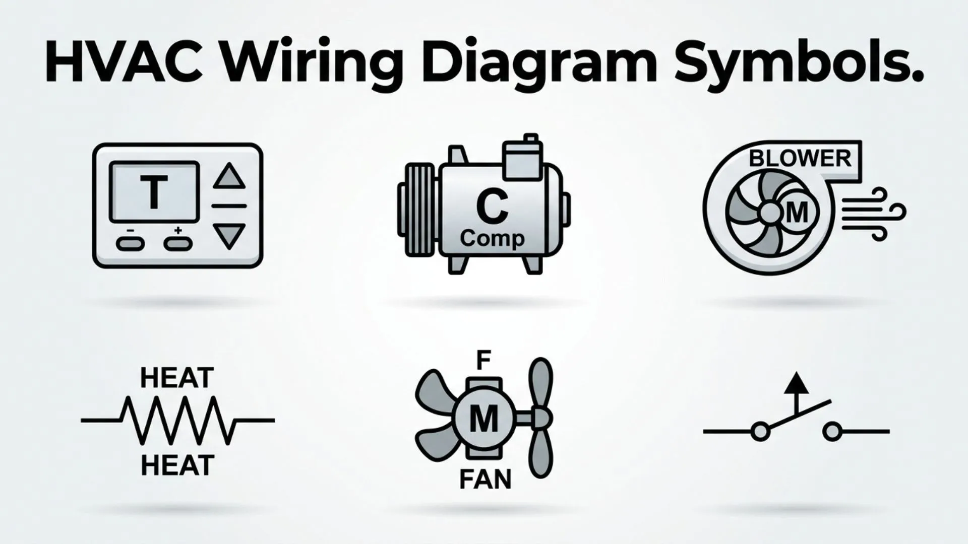
HVAC wiring diagram symbols are essential for understanding how heating, ventilation, and air conditioning systems operate. Whether you’re an HVAC technician, electrician, student, engineer, or DIY homeowner, knowing these symbols can help you read wiring diagrams accurately, troubleshoot electrical problems, and install equipment safely.
Instead of relying on lengthy descriptions, wiring diagrams use standardized symbols as a universal communication system. These symbols represent electrical components such as switches, relays, transformers, thermostats, motors, capacitors, and safety devices. Once you understand what each symbol means, even a complex HVAC schematic becomes much easier to interpret.
This comprehensive guide explains HVAC wiring diagram symbols, their meanings, history, common categories, applications, and best practices for reading electrical diagrams. You’ll also learn common mistakes to avoid and discover practical tips for using HVAC schematics with confidence.
HVAC Wiring Diagram Symbols (Meaning and Overview)
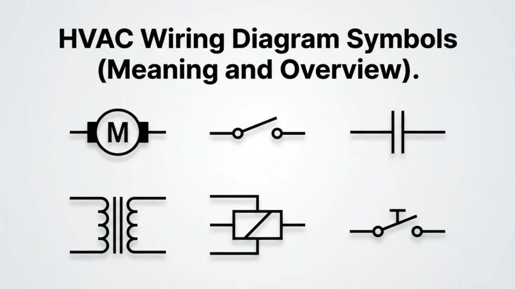
HVAC wiring diagram symbols are standardized graphical representations used to identify electrical components and connections in heating and cooling systems. Rather than drawing realistic pictures of equipment, diagrams use simple icons and signs to represent each device.
These symbols allow technicians worldwide to interpret electrical circuits regardless of language differences. Every symbol meaning is based on industry standards established by organizations such as ANSI (American National Standards Institute), IEC (International Electrotechnical Commission), and NFPA (National Fire Protection Association).
An HVAC wiring diagram typically illustrates:
- Power supply
- Control circuits
- Thermostat wiring
- Safety switches
- Relays
- Contactors
- Motors
- Compressors
- Capacitors
- Transformers
- Sensors
- Ground connections
Each visual representation helps explain how electricity flows through the HVAC system.
History and Origin
Electrical schematic symbols have existed since the late nineteenth century, shortly after electrical systems became common in homes and industries.
As heating and cooling technology evolved, manufacturers needed a consistent method for documenting increasingly complex electrical circuits. Early HVAC equipment often included hand-drawn wiring diagrams with custom symbols, but this created confusion between manufacturers.
Over time, standardized electrical symbols became widely adopted. Organizations such as ANSI and IEC introduced common schematic conventions that made wiring diagrams easier to understand across different brands and countries.
Modern HVAC systems continue using these standardized symbols in:
- Installation manuals
- Service guides
- Wiring schematics
- Equipment documentation
- Digital maintenance software
- Training materials
Although software now creates most diagrams digitally, the symbols themselves remain largely unchanged because their universal design has proven highly effective.
Types of HVAC Wiring Diagram Symbols
HVAC wiring diagrams contain several categories of symbols, each representing a different part of the electrical system.
Power Supply Symbols
Power supply symbols identify where electricity enters the HVAC system.
Common examples include:
- AC power source
- Single-phase power
- Three-phase power
- Neutral connection
- Ground connection
- Circuit breaker
These symbols establish the starting point of the electrical circuit.
Control Device Symbols
Control devices regulate HVAC operation.
Common control symbols include:
- Thermostat
- Selector switch
- Push button
- Limit switch
- Pressure switch
- Float switch
- Time delay relay
These components help automate system performance while maintaining safety.
Motor and Mechanical Component Symbols
Motors drive many HVAC components.
Common motor symbols include:
- Blower motor
- Condenser fan motor
- Inducer motor
- Compressor motor
- Pump motor
Each symbol indicates where electrical energy powers mechanical movement.
Protection Symbols
Safety devices protect equipment from electrical damage.
Examples include:
- Fuse
- Overload protector
- Circuit breaker
- Thermal protector
- High-pressure switch
- Low-pressure switch
These symbols highlight essential protective features within the system.
Common HVAC Wiring Diagram Symbols and Their Meanings
Understanding the most common symbols makes reading wiring diagrams much easier.
Thermostat Symbol
The thermostat controls heating and cooling by monitoring indoor temperature.
On wiring diagrams, terminals often appear as:
- R – 24V power
- C – Common wire
- Y – Cooling
- W – Heating
- G – Indoor fan
- O/B – Heat pump reversing valve
These terminal designations are standard communication symbols used across many HVAC systems.
Transformer Symbol
The transformer converts high-voltage electricity into low-voltage control power, typically reducing 120 or 240 volts to 24 volts.
Its schematic usually shows two coils representing the primary and secondary windings.
Capacitor Symbol
Capacitors help start and run electric motors.
Two common types include:
- Start capacitor
- Run capacitor
The capacitor symbol generally consists of two parallel plates, although polarized capacitors use a slightly different visual representation.
Contactor Symbol
A contactor functions as a heavy-duty electrical switch.
When the thermostat sends a low-voltage signal, the contactor closes, allowing high-voltage power to reach the compressor and condenser fan motor.
Relay Symbol
Relays control circuits automatically.
Their diagrams include:
- Relay coil
- Normally open contacts
- Normally closed contacts
These symbols demonstrate how one electrical circuit controls another.
Compressor Symbol
The compressor is the heart of an air conditioning or heat pump system.
The wiring symbol identifies its electrical terminals and motor connections.
Fan Motor Symbol
Fan motors circulate indoor and outdoor air.
Separate symbols often identify:
- Indoor blower
- Outdoor condenser fan
- Exhaust fan
- Ventilation fan
Ground Symbol
Ground symbols indicate electrical safety connections.
Proper grounding helps prevent electrical shock and protects HVAC equipment from faults.
Understanding HVAC Wiring Colors
Although wiring diagrams focus on symbols, wire colors provide additional information.
Common HVAC wire colors include:
- Red – 24V power
- White – Heating
- Yellow – Cooling
- Green – Fan
- Blue or Black – Common
- Orange – Reversing valve
- Brown – Capacitor connection
Keep in mind that wire colors can vary between manufacturers. Always verify using the equipment’s wiring diagram rather than relying solely on color.
Reading an HVAC Wiring Diagram
Learning to read diagrams becomes easier by following a structured approach.
Identify the Power Source
Locate the incoming electrical supply first.
Determine whether the equipment uses:
- 120 volts
- 208 volts
- 230 volts
- 240 volts
- Three-phase power
Follow the Circuit Path
Trace electrical current from the power source through switches, relays, motors, and back to neutral or ground.
This approach simplifies troubleshooting.
Understand Component Labels
Manufacturers often use abbreviations alongside symbols.
Examples include:
- COMP – Compressor
- FAN – Fan motor
- XFMR – Transformer
- TSTAT – Thermostat
- CAP – Capacitor
- CB – Circuit breaker
Separate High Voltage and Low Voltage
Most HVAC diagrams distinguish between:
- High-voltage circuits
- Low-voltage control circuits
Keeping these sections separate reduces confusion.
Common Uses and Applications
HVAC wiring diagram symbols serve many practical purposes.
Equipment Installation
Installers use wiring diagrams to connect equipment correctly during installation.
Troubleshooting
Service technicians locate faulty components by following electrical paths shown in the diagram.
Maintenance
Preventive maintenance becomes easier when technicians understand control circuits and component locations.
Technical Training
HVAC schools teach students how to interpret electrical symbols before working on live systems.
Manufacturing
Equipment manufacturers use standardized diagrams to ensure consistency across product lines.
Engineering Design
Mechanical and electrical engineers rely on HVAC schematics when designing commercial buildings and industrial facilities.
Symbolism and Importance
Although HVAC symbols are technical rather than artistic, they hold significant value as communication tools.
Every icon represents an electrical function without requiring lengthy explanations.
Their symbolic significance includes:
- Universal understanding
- Improved troubleshooting
- Faster equipment installation
- Greater workplace safety
- Reduced wiring errors
- Consistent technical documentation
Unlike decorative symbols or typography symbols, HVAC wiring symbols are functional representations that eliminate ambiguity in electrical drawings.
How to Use HVAC Wiring Diagram Symbols
If you’re learning HVAC electrical systems, these best practices will improve accuracy.
Learn Standard Symbols First
Focus on common components before studying advanced industrial systems.
Read the Legend
Many manufacturers include a legend explaining unique symbols used in their diagrams.
Trace One Circuit at a Time
Avoid trying to understand the entire schematic at once.
Following a single electrical path makes diagrams much easier to interpret.
Verify Before Working
Never assume a symbol represents the same component across every manufacturer.
Always compare the wiring diagram with the service manual.
Use Safe Electrical Practices
Understanding symbols does not replace electrical safety procedures.
Always disconnect power and verify voltage before servicing HVAC equipment.
Interesting Facts
- HVAC wiring diagrams use standardized symbols recognized worldwide.
- Many electrical symbols have remained nearly unchanged for decades.
- Digital CAD software automatically inserts standardized HVAC schematic symbols.
- Large commercial HVAC systems may contain hundreds of individual electrical symbols.
- Modern smart thermostats still rely on many traditional terminal designations.
- Electrical schematics are designed to explain function rather than physical component location.
- Unlike Unicode symbols or text symbols used in digital typography, HVAC symbols exist primarily for technical documentation.
- Professional certification exams often test a technician’s ability to interpret wiring diagrams accurately.
Common Mistakes or Misconceptions
Confusing Wiring Diagrams with Pictorial Diagrams
A wiring diagram shows electrical connections rather than the physical placement of components.
Assuming Every Manufacturer Uses Identical Layouts
Although symbols are standardized, diagram layouts vary by manufacturer.
Ignoring Safety Symbols
Overlooking grounding, overload protection, or disconnect switches can create serious hazards.
Depending Only on Wire Colors
Wire colors may differ between systems, making the wiring diagram the most reliable reference.
Misidentifying Relay Contacts
Confusing normally open and normally closed contacts is one of the most common troubleshooting mistakes.
Frequently Asked Questions
What are HVAC wiring diagram symbols?
HVAC wiring diagram symbols are standardized graphical icons representing electrical components such as thermostats, relays, transformers, motors, switches, and capacitors.
Why are HVAC wiring symbols important?
They provide a universal method for understanding electrical circuits, simplifying installation, maintenance, and troubleshooting.
Are HVAC wiring symbols standardized?
Yes. Most manufacturers follow standards developed by organizations such as ANSI and IEC, although some proprietary variations may exist.
Is a wiring diagram the same as a schematic?
Not exactly. Wiring diagrams emphasize electrical connections, while schematics focus on circuit operation. Both use many of the same symbols.
Can homeowners read HVAC wiring diagrams?
Yes, with basic electrical knowledge and proper safety precautions. However, servicing live electrical systems should be left to qualified professionals.
What is the most common HVAC wiring symbol?
The thermostat symbol is among the most frequently used because nearly every HVAC system depends on thermostat control wiring.
Do HVAC symbols change for heat pumps?
Most symbols remain the same, although heat pump diagrams include additional components such as reversing valves and defrost controls.
Conclusion
HVAC wiring diagram symbols are the foundation of electrical communication within heating and cooling systems. They transform complex circuits into clear, standardized diagrams that technicians, engineers, installers, and students can understand regardless of equipment brand or language.
Learning the meaning of common symbols such as thermostats, transformers, relays, contactors, motors, capacitors, and safety devices makes installation, troubleshooting, and maintenance significantly more efficient. Combined with proper safety practices and manufacturer documentation, these symbols provide an accurate roadmap for understanding how HVAC systems function.
Whether you’re beginning an HVAC career or simply expanding your technical knowledge, mastering wiring diagram symbols is an essential skill that improves accuracy, reduces mistakes, and builds confidence when working with modern heating and cooling equipment.

Daniel Carter is a writer and researcher focused on symbols, their meanings, origins, and practical uses. He enjoys turning complex symbolic concepts into simple, easy-to-understand explanations for everyday readers. Through his work, Daniel explores cultural, technical, historical, and commonly used symbols, helping readers understand what they mean and where they are used.
His work includes The Complete Guide to Symbols, Understanding Symbols and Their Meanings, and A Visual Guide to Common Symbols.